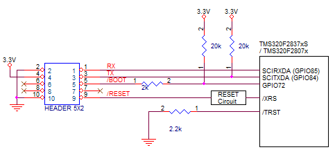
- Factory default setting is assumed
- power pin (#4) of easyDSP 5x2 header should be connected to 3.3V
- connect SCIRXDA = GPIO85, SCITXDA = GPIO84
- In case there is a reset IC between easyDSP /RESET and MCU /XRS, it should transfer easyDSP /RESET signal to MCU /XRS within 0.5sec
- TX/RX pins are directly connected to MCU pins
- In case you insert buffer IC between easyDSP header and MCU, place buffer IC directly to easyDSP header so that all resistors can be connected to directly MCU
- /RESET pin is connected to reset generation circuit of MCU board
(Time duration of /RESET pin is around 500msec)
- In case you use pull-up resistor to each pin, the value of pull-up resistor should be higher than a few kilo ohm since there is 100Ω series resistor inside easyDSP pod
- You can use the boot pin GPIO72 in your program
Please be careful when you use your own pull-up or pull-down resistor on the easyDSP signal pins. Please use appropriate filter circuit to your reset generation circuit to prevent unintentional reset generation.